
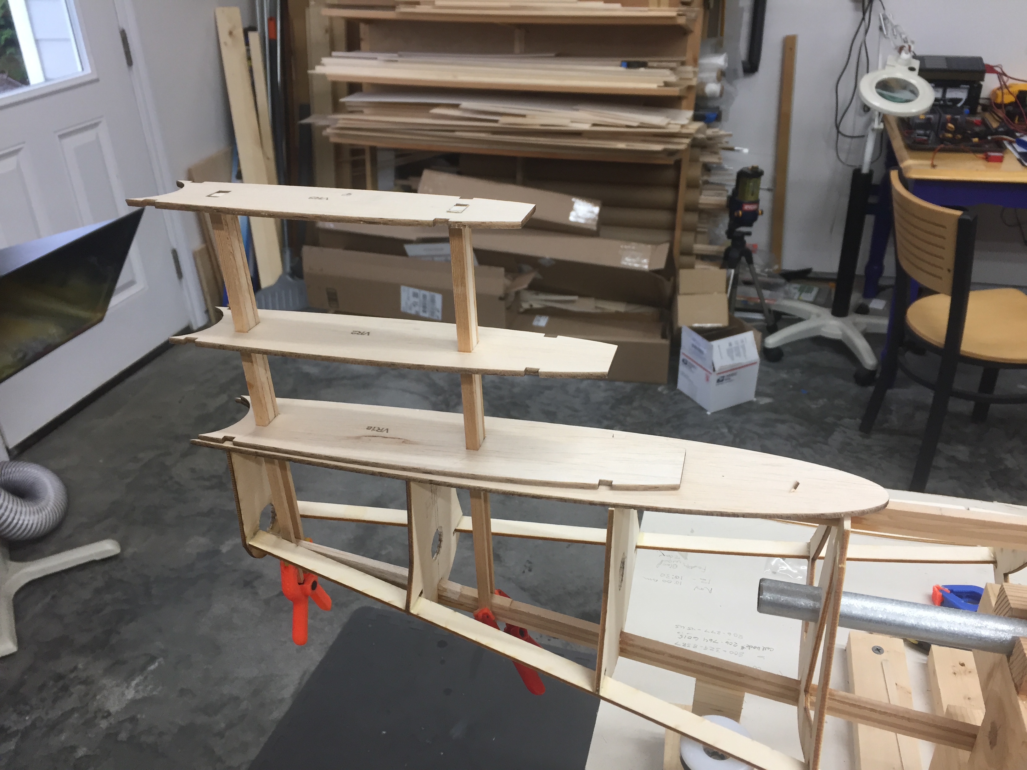
Here we have Jim’s CAD of the stabilizers and how the horizontal stab’s inner ribs will slip over the mounting box.
Robert Ball - Page 2
Here we have Jim’s CAD of the stabilizers and how the horizontal stab’s inner ribs will slip over the mounting box.
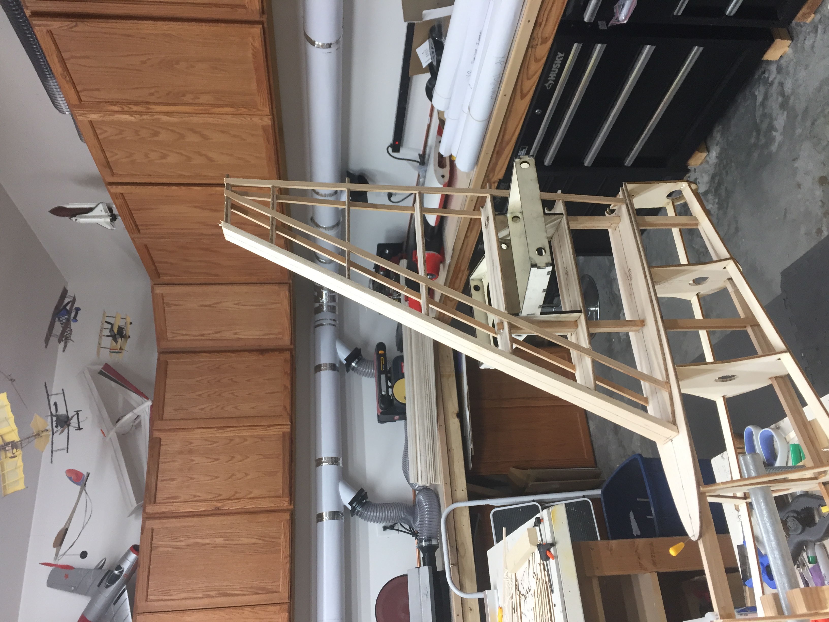
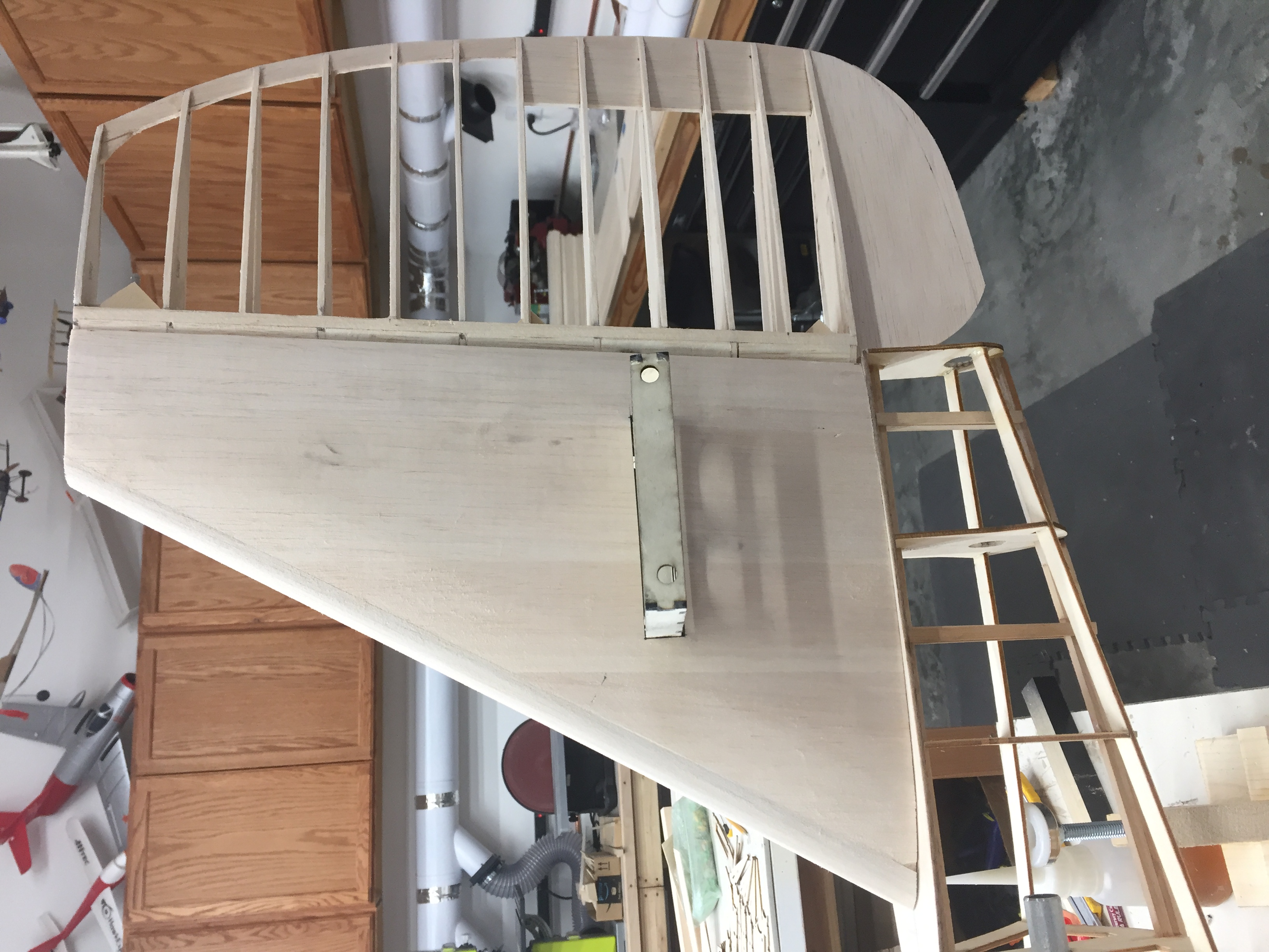
Stab is sheeted and the rudder is hinged. The rudder will be covered in fabric as per the real aircraft. Pull/pull cables will drive the rudder from a servo mounted in the flap well.
December 7, 2019
We are advancing a bit every day, this past week the outer wing panels were framed up and the shape of forward nacelles has been started.
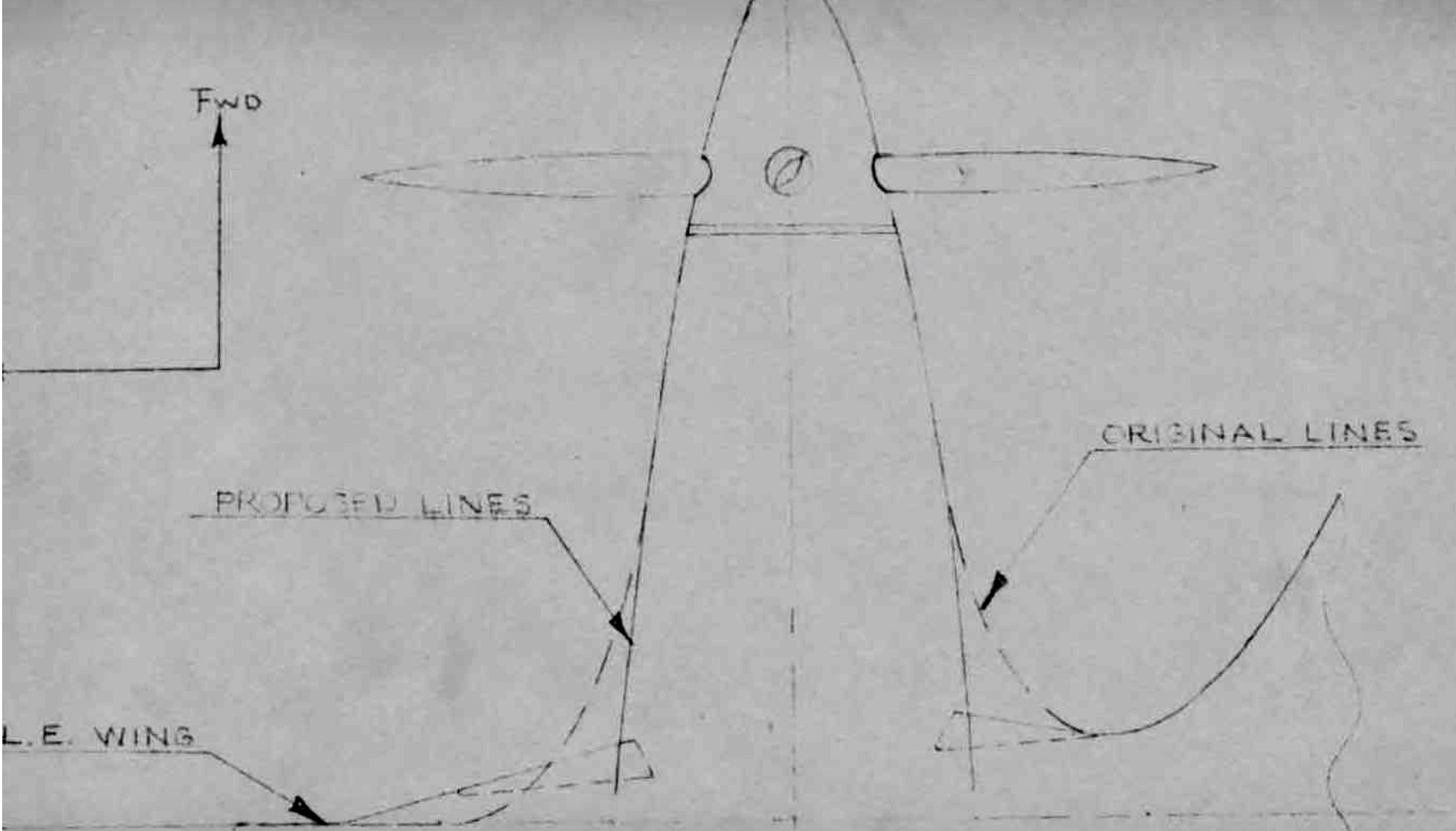
On this top view of a nacelle you can see the original lines of the cooling intakes and the proposed changes required because of insufficient cooling airflow to the Continental flat 12s. The model was framed up for the original version but I decided to build it as it was configured on its last flight.
Sides were tapered 7 degrees and tilted in on the bottoms 10 and 13 degrees (see second drawing)
Here is the outside of the port nacelle after the original framing was cut away and the new side glued in place, 7 degrees taper back to front and 10 degrees top to bottom.
After putting the side in place I fashioned a removable former to shape the outside air inlet, once the planking is in place and a block of Balsa sanded to shape the leading edge
former will be removed.
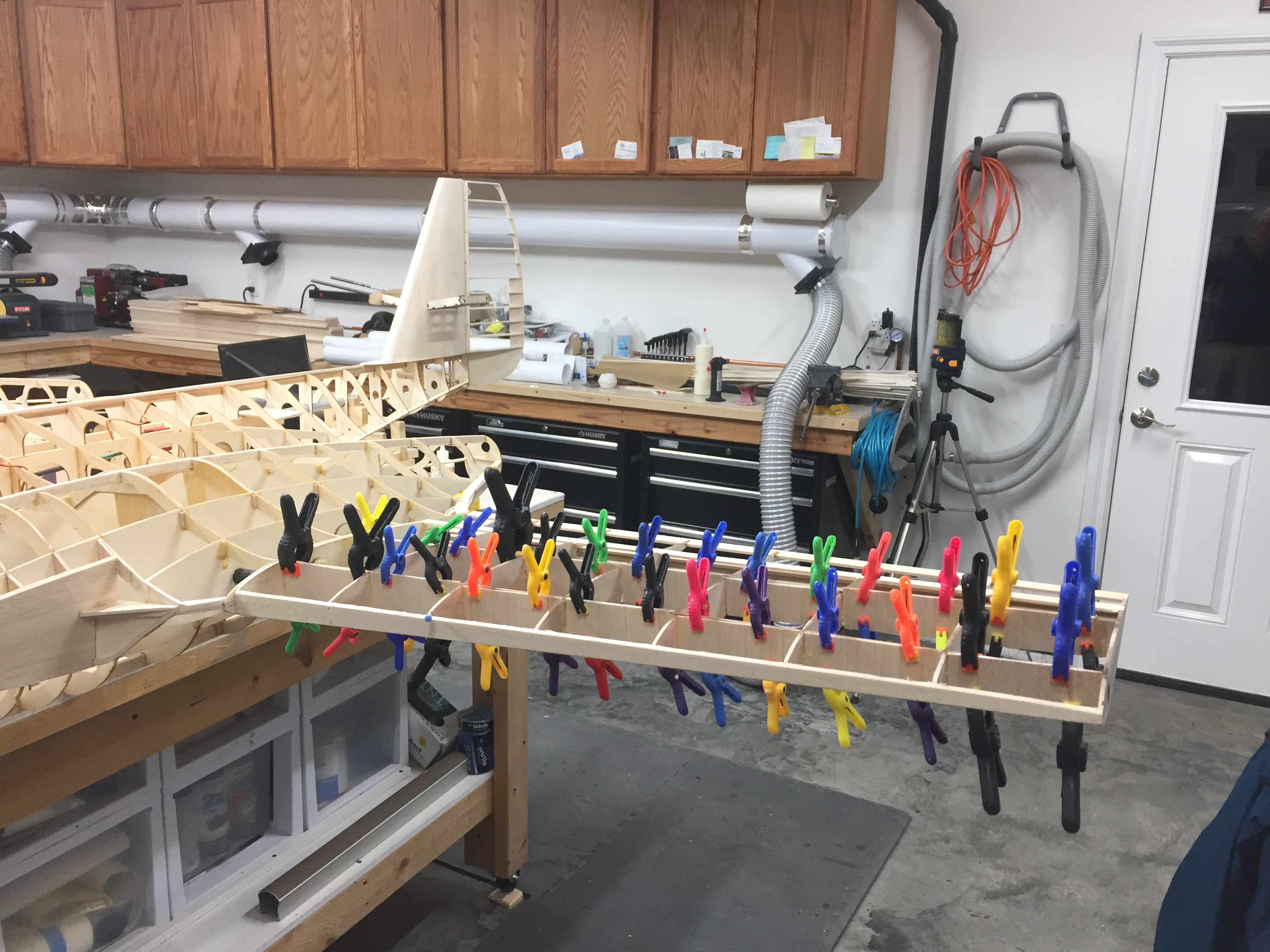
The outer wing panels were formed up on a 5/8” carbon fiber tube and a .300” arrow shaft used as an anti rotation tube. Simple blocks of wood were cut to the rib spacing, notched out where glue might creep into and laid out square. The wing washout was built in by Jim and extends from root to tip. As it sits on the airframe the washout at root is 0 degrees and the tips 3 degrees.
Port wing panel with shear webs clamped in place.
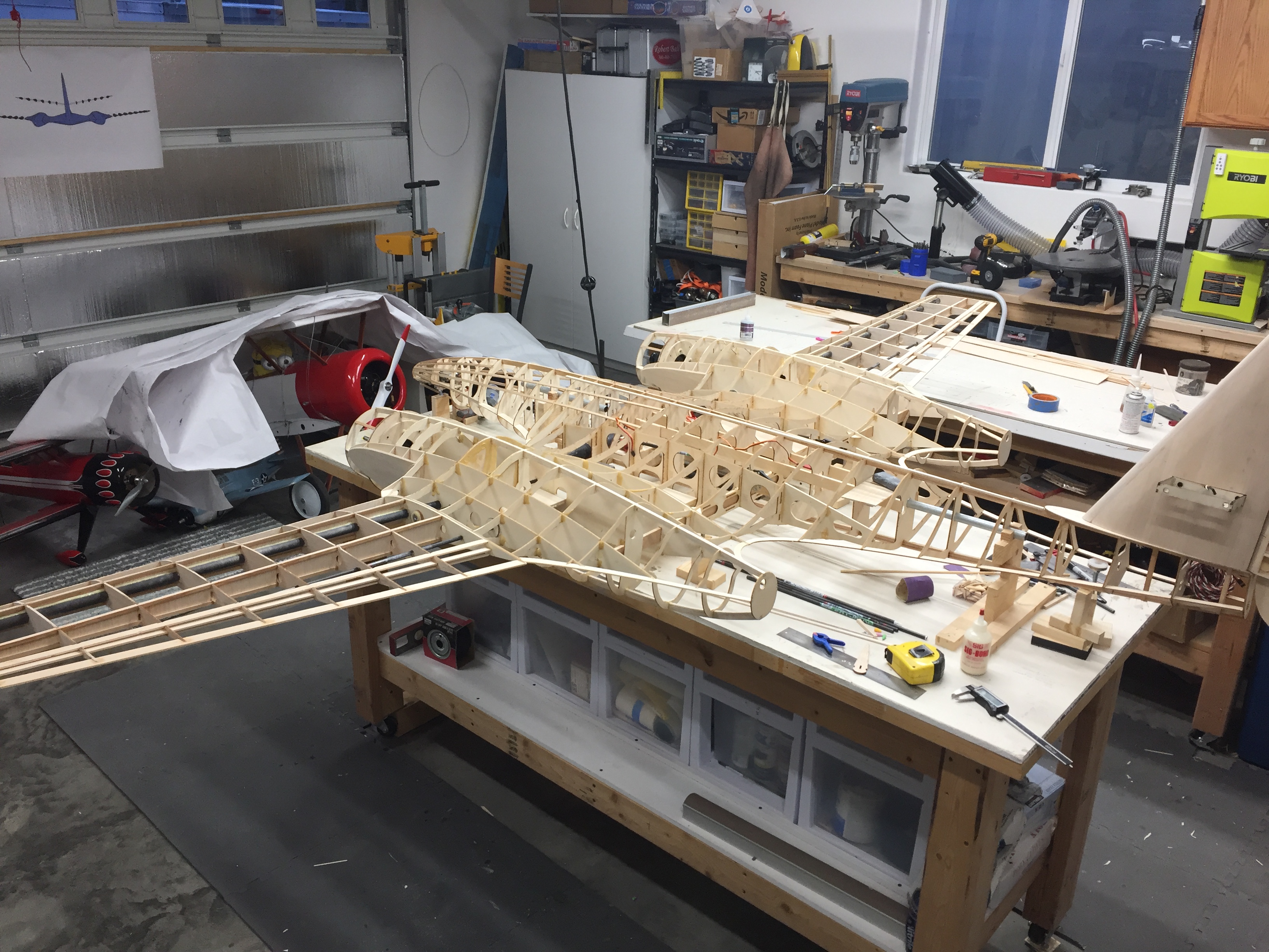
It’s starting to look like an airplane now!
Once I build the horizontal stabs and fit in place I’ll be able to square the tail and then begin planking the upper fuselage.